
Understanding working principle and failure modes of anchors
1. What is Post-Installed Anchor?
Post-installed anchors help providing flexibility for modifications, repair, addition of new steel structure to existing concrete structures cast at a previous point in time ensuring the connection is securely established. This technology can be used in a wide range of applications including structural and non-structural connections with simple installation and contribution to sustainable construction practices complying to modern standards. For steel to concrete (S2C) connections, post-installed anchors create reliable, safe and code compliant solution maintaining structural integrity of primary, secondary, temporary structural and non-structural applications.

2. Anchor Working Principle
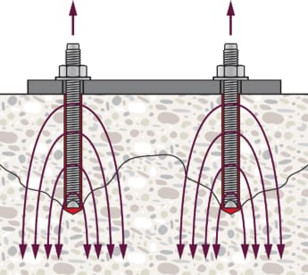
Fastening systems transfer applied loads to the base material in different ways. Under both tension (Fig. 2.1a) and shear loading (Fig. 2.1b), the load transfer mechanism involves the utilization of concrete tensile strength. We refer in this case to fastening design theory in opposition to the reinforced concrete theory, where the concrete tensile strength is usually neglected in design. The load-transfer mechanisms for various fastening systems are typically identified as mechanical interlock, friction, and adhesive bond mechanisms.

Mechanical interlock/keying defines the working principle where the load is transferred by means of a bearing surface between the anchor and the base material (see Fig. 2.2a). Some post-installed fasteners develop a mechanical interlock between the anchor and the base material. To achieve this, a cylindrically drilled hole is modified to create a notch, or undercut, of a specific dimension at a defined location either by means of a special drill bit, or by the undercutting action of the anchor itself. An example is the Hilti HDA.
Friction mechanism is the load-transfer mechanism typical of systems where expansion force is generated by a clip or a wedge pressed against the walls of the borehole during the installation process. Frictional resistance equilibrates the external tension force on anchors. The tensile load, N, is transferred to the base material by friction, R (Fig. 2.2 b). An example is the Hilti HST4.
Adhesive bond mechanism involves the transfer of the external load to the concrete base material via an adhesive bond (see Fig. 2.2 c)). The forces are transferred from the anchor element (e.g., a threaded rod) to the mortar via mechanical interlocking and to the base material via a combination of micro-interlock and chemical adhesion between the mortar and the lateral surface of the borehole. An example is the Hilti HIT-RE 500 V4 & HAS threaded anchor rod.

3. Failure Modes Under Tension Loading
Anchors can fail in various manner if the acting load exceeds their resistance. The failure modes can be distinguished for different loading directions, tension and shear. Failure modes can further be distinguished between the rupture of the fasteners (steel failure) and the failure of the base material or of the interface between the anchor and base material (concrete failure). Different steel and concrete related failure modes are described below.

Steel failure occurs when tension stresses induced by the acting load in the smallest cross section of the anchor exceed the ultimate steel resistance (Fig. 3.2).

To obtain a higher resistance to this failure mode, one of these strategies (or a combination of them) can be followed:
- Increase the number of anchors;
- Select a higher steel strength for the anchor or
- Increase the anchor diameter.
Concrete cone failure is characterized by the formation of a cone-shaped fracture surface originating in the load-transfer zone of the anchor and radiating towards the concrete surface with an angle of approx. 35° between the inclined radial crack and concrete surface (Fig. 3.3). The failure mode is also referred as concrete break-out under tension loading.

To obtain a higher concrete cone resistance, one of the strategies (or a combination of them) can be followed:
- Increasing the spacing between anchors;
- Increasing the embedment depth of anchors;
- Using a base material of higher concrete strength class.
Pull-out failure occurs when the entire anchor is pulled out of the drilled hole without significant damage of the base material (Fig. 3.4).

To improve the pull-out resistance one of the strategies (or a combination of them) can be followed:
- Choice of an anchor with higher resistance;
- Increasing the anchor diameter;
- Increasing number of anchors.
Combined pull-out and concrete cone failure is applicable to bonded anchors only. This failure is a combination of the pull-out due to loss of bond between the anchor and the concrete and as a shallow concrete cone close to the concrete surface (Fig. 3.5).

Concrete splitting failure is caused by the hoop stresses around the anchor which originate from local load transfer and expansion forces that exceed the concrete tensile resistance (Fig. 3.6). This failure mode can occur during the installation of an anchor if the minimum spacing, edge distances or member thicknesses are not kept or due to loading in near edge/close to spacing conditions.

Splitting failure during installation can be avoided by maintaining the following conditions as given in the relevant ETA:
- Minimum edge distance
- Minimum spacing between anchors
- Minimum base material thickness.
Effective strategies to increase the resistance against splitting failure due to loading are:
- Increasing edge distance and spacing between fasteners;
- Reducing the embedment depth; and
- Accepting that splitting cracks will happen and re-run the design assuming cracked concrete and accounting for sufficient reinforcement in the base material to limit their width.
Concrete blow-out failure is a result of high-bearing pressure generated in the load transfer area of the anchor (Fig. 3.7). These high-bearing stresses cause bursting forces transverse to the load direction, creating a concrete break-out on the side face of the member. This failure mode may be decisive in near edge conditions and large embedment that can usually be achieved with headed studs, but usually not with post-installed anchors. To avoid this failure, edge distance needs to be increased.

4. Failure Modes Under Shear Loading
Post-installed anchors can experience steel or concrete related failures under shear loading with or without lever arm.

Steel failure occurs when tension stresses induced by the acting load in the smallest cross section of the anchor exceed the ultimate steel resistance (Fig. 4.2). If the shear load is applied with a lever arm the resistance is reduced due to the additional tension stress arising from the caused bending moment.

To increase the resistance against this failure mode:
- Select a more resistant steel material;
- Increase the diameter of the anchor;
- Increase the number of anchors.
Concrete pry-out failure primarily occurs in cases of limited embedment depth of anchors. It is caused by rotation of the fastener and the catenary tension force generated in the anchor bolt as a result of lateral deformation and the eccentricity between the acting shear force and the resultant resisting force in the concrete (Fig. 4.3). Pry-out failure is dependent on the resistance value for cone break-out and pull-out failure. Hence, if resistance for those failure modes can be increased, resistance against pry-out will also be higher.

Concrete edge failure occurs under shear load when the anchors are close to an edge in the loading direction. It is characterized by the formation of a cone shaped fracture surface originating at the anchor shaft and radiating towards the concrete edge with an angle of approx. 35° (Fig. 4.4). This failure mode is also referred as concrete break-out under shear loading.

The resistance against this failure mode can be improved by increasing:
- The edge distance for first row of anchors;
- The embedment depth of anchors;
- The spacing between anchors in a group; and
- Diameter of anchors.
5. Conclusion
In conclusion, post-installed anchors are critical components used to attach structural and non-structural elements to concrete. Hence, their failure can lead to serious safety hazards. Understanding and addressing the failure modes properly is crucial for structural safety, performance, and compliance. Code compliant design of anchors supported by quality assurance for the required resistance against tension and shear related failure modes can help to ensure structural integrity, prevents safety hazards, avoids costly repairs and time.
Please go through Hilti Steel-to-Concrete Handbook for more detail information: https://www.hilti.com.my/engineering/article/hilti-handbook-for-steel-to-concrete-connections-using-post-installed-systems/gijgeo
To start designing post-installed anchor, visit PROFIS Engineering at https://profisengineering.hilti.com/
6. REFERENCES
[1] EN 1992-4:2018: Eurocode 2 - Design of concrete structures - Part 4: Design of fastenings for use in concrete, Brussels: CEN, 2018.
[2] S2C Handbook: Steel to concrete connections using Post-installed systems, Schaan: Hilti Corporation, 2024.
Click here to download the S2C Handbook
For more information, please leave a comment on this article or visit to our Engineering Centre
For further enquiry or clarifications, please feel free to reach out to us at my.engineering@hilti.com
Additional technical resources:
On-demand : Steel to Concrete (S2C) Connection
General Notes, Typical Details & Specification Text
Article : Rigid vs Flexible Baseplate Assumptions
Article : Cracked Concrete Consideration in Design of Post-Installed Anchor
Article : Ensuring Fastener Safety with the Use of Quality Threaded Rod
Article : Secure the Structure with Proper Seismic Design of Anchors
