
Improved design for anchors under shear loading
1. Introduction and background
Fasteners play a key role in ensuring the performance and durability of structures, with their use in the construction industry evolving significantly over the past two decades. It is now common practice to attach structural and non-structural elements to existing reinforced concrete (RC) members by using post-installed connections. Depending on design requirements for the structure and especially the fastening, the anchor configuration can vary to a point where the regular arrangements specified in national and international fastening design guidelines do not suffice. For instance, critical structural connections positioned close to the edge and loaded in shear may need more flexibility in anchorage design that often exceeds the current scope of the available design standards. The design of connections further requires flexibility when sustaining load combinations for static and seismic, and often due to the geometrical limitations. For the complex and unique projects, fastening design may require exceeding the limits set forth by design standards such as EN 1992-4 [1], whilst maintaining the same reliability of the fasteners and the overall connection.
This article presents an expansion to the design provisions contained in the current EN 1992-4 [1] under the “Hilti SOFA Method” (Solutions for Fastening) which allows shear distribution to more rows beyond the front one for concrete edge break-out verification. This expansion focuses on the design of anchors beyond the standard approach in EN 1992-4 [1] and provides more flexibility in consideration of the number of anchors in a group when loaded in shear close to one or more concrete edges. The paper outlines the current scope of design in EN 1992-4 [1] and limitations (Chapter 2), the state-of-the-art approach for shear load distribution according to fib Bulletin 58 [2] (Chapter 3), expansion of the anchor layout and shear load distribution as per SOFA (Chapter 4 ), verification of resistances against tension and shear loading (Chapter 5), and conclusions.

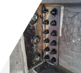
Fig. 1.1: Critical anchor arrangements at jobsite
2. Anchor configurations and the design provisions covered by EN 1992-4
EN 1992-4 [1] provides provisions for the design of fastenings for use in concrete. These provisions reflect the foundational empirical experience that account for various uncertainties to ensure a high level of safety, but ones that may not always lead to the most optimized design. One consequence of the foundational empirical evidence is the applicability of the design provisions of EN 1992-4 [1] is the limitation of the anchor group configurations, shown in Fig. 2.1 and Fig. 2.2. An anchor located at an edge distance >=max(10h_ef;60d_nom) is deemed as “far from the edge”, otherwise it is considered as “near to the edge”. In “far from edge” conditions, the check for concrete edge break-out under shear loading may be omitted. Fig. 2.1 shows permitted anchor configurations for anchor groups without hole clearance for all edge distances and load directions, and fastenings with normal hole clearance according to EN 1992-4 [1], Table 6.1 situated far from edges for all load directions and situated near to edge loaded in tension only. Fig. 2.2 shows covered anchor configurations for groups with a hole clearance situated near to edge for all load directions.

Fig. 2.1: Anchor groups without hole clearance for all edge distances covered by EN 1992-4

Fig. 2.2: Anchor groups with / without hole clearances situated near to edge covered by EN 1992-4
2.1 Anchor layouts and static shear load distribution
EN 1992-4 [1] allows engineers to design anchor layout options up to 3x3. The term “hole clearance” refers to the annular gap between the anchor and the fixture (or baseplate).
Shear applied on the baseplate is distributed to the anchors based on its effectiveness to resist shear load, which in turn is dependent on the hole clearance and the edge distance. If the hole is slotted in the direction of the shear force, then the anchor does not resist the shear loads. All anchors are considered to resist shear load if it acts parallel to the edge, the anchors are subject to torsion, or the anchors are located far from the edge,  . For steel and pry-out checks, all anchors of an anchor group are considered effective. For concrete edge failure check, only the anchors close to the edge,
  are assumed to resist the shear that acts perpendicular or parallel to the edge.
Table 2.1 shows the static shear load distribution through the anchors close to edge conditions according to EN 1992-4 [1].
Table 2.1: Shear load distribution for anchors close to edge, according to EN 1992-4
Fig. 2.3 and Fig. 2.4 describe how shear acts on the anchors and how anchors participate in sharing the shear load. In the case of a group of anchors loaded parallel to the edge, the shear is divided equally amongst all anchors with verification for edge breakout required only for the anchors nearest to edge. For a group of anchors loaded perpendicular to the edge, the shear load is divided equally between the row of anchors nearest to the edge, with any components of shear acting away from the edge are neglected when verifying resistance to concrete edge breakout, i.e., shear must be resisted entirely by the front row. 
EN 1992-4 [1] allows anchors in base plates extending beyond the concrete with hole clearance as shown in Fig. 2.5.

Fig. 2.5: Anchors with hole clearance in a baseplate extending beyond the concrete edge
2.2 Anchor layouts and seismic load distribution
The anchor layout and seismic shear load distribution in EN 1992-4 [1] follow the same provisions as stated in the Section 2.1. Since the concrete edge breakout checks are ignored when anchors loaded in shear are far from the edge or when shear is directed away from the edge, all layouts in Table 2.1 are permitted.
In summary, EN 1992-4 [1] includes the scope of design of anchors up to 3x3 and shear distribution to the front row of anchors. The fib Bulletin 58 [2] “Design of anchorages in concrete” contains additional design provisions for resistance against shear load.
3. State-of-art approach for shear load distribution in FIB Billetin 58
As covered in Section 2.1 of this document, EN 1992-4 [1], Section 6.2.2.2 specifies just one approach to determine which anchors in a group participate in resisting shear acting towards an edge, with no or normal hole clearance determining which anchor group configuration can or cannot be positioned near an edge. The fib Bulletin 58 [2], Section 4.3.1.3 includes another, less restrictive approach to determine which anchors in a group participate in resisting shear, which is independent of: (1) the hole clearance between the baseplate and anchors; and (2) the anchor group configurations.
In both EN 1992-4 [1] and fib Bulletin 58 [2], when an anchor group situated near an edge is loaded in shear perpendicular to that edge, all anchors participate in resisting shear failure in steel and concrete pry-out, with the provisions in the former only allowing anchors closest to the edge (front row) effectively resist shear failure in concrete edge breakout. The fib Bulletin 58 [2] does not restrict edge breakout solely to anchors in the front row and allows anchors in the second and / or third rows parallel to the edge to also participate in resisting concrete edge breakout. Here, the governing failure plane is not always the front row, and concrete edge breakout must be verified for all failure planes, as illustrated by Fig. 3.1.
Distinction is made, however, in relation to hole clearance: under normal hole clearance, the assumed failure plane for edge breakout should remain at the front row of anchors to avoid an unacceptable loss in serviceability.

While the fib Bulletin 58 [2] allows distribution of shear beyond the front rows for edge breakout, the anchor groups are still restricted to 3x3 grid without hole clearance and to 2x2 with hole clearance, see Figure 4.3-1 of [2]. Anchor layouts beyond 3x3 and irregular configuration, such as triangular and circular, are not covered in either EN 1992-4 [1] or fib Bulletin 58 [2].
--> Continued to Part 2
